


Establish a clean-loop baseline
Record normal turbidity after commissioning and coolant stabilization.
Rika Sensor is a weather sensor manufacturer and environmental monitoring solution provider since 2010
RIKA SENSOR / DATA CENTER LIQUID COOLING
Online turbidity trends for CDU liquid cooling systems.
OVERVIEW
Temperature, pressure and flow show how a cooling loop is operating. The RK500-07LC adds another view: whether the cleanliness of the circulating coolant is beginning to change.
Fine particles, corrosion products and commissioning debris may circulate through CDU piping, manifolds, quick connections and cold plates. Tracking turbidity online can help teams notice a sustained change and decide when further inspection is justified.
KEY POINT
Turbidity is a coolant cleanliness trend indicator. It does not identify the contaminant, particle size or source by itself. Its value comes from establishing a clean baseline and detecting meaningful change over time.
APPLICATION
Record normal turbidity after commissioning and coolant stabilization.
Look for sustained movement rather than reacting to every isolated reading.
Review operating conditions and check for possible particle or corrosion sources when the trend shows a sustained change.
PRODUCT FEATURES
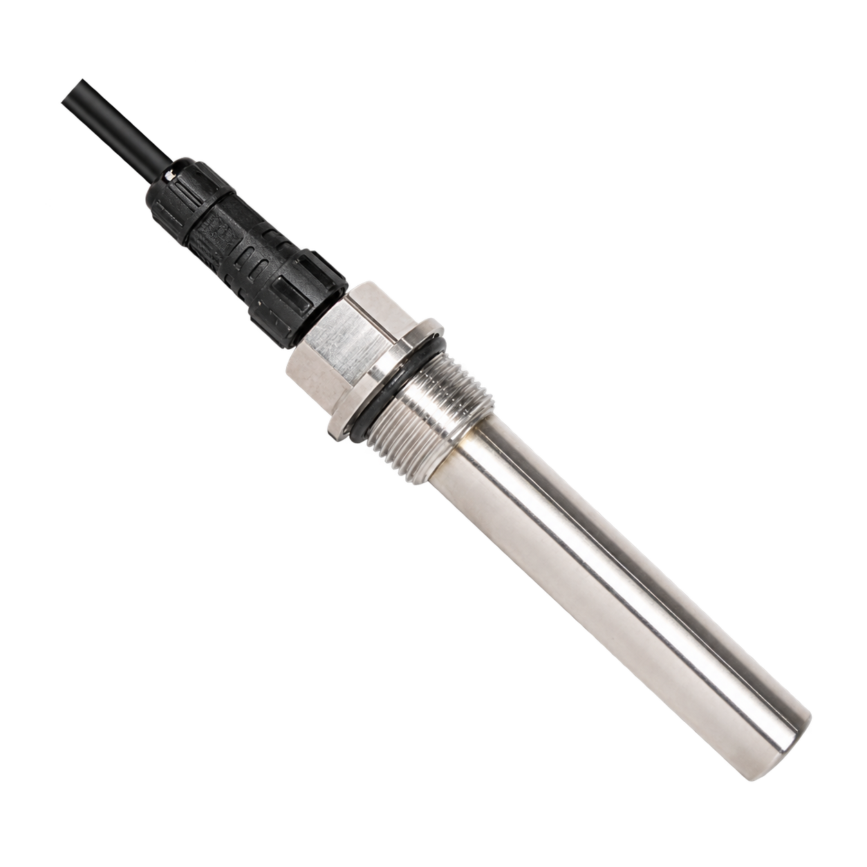
Uses the 90° nephelometric method to measure turbidity online, with 0-10 NTU and 0-100 NTU range options and a specified response time of 1 second.
Overall 316L stainless steel construction with a sapphire measurement window. The specified applicable media include deionized water, PG25 and EG25.
No external modules are required. Simultaneous 4-20 mA and RS485 outputs connect to compatible monitoring equipment, with a 7-30 VDC supply and power consumption below 0.2 W.
TECHNICAL DATA
| Measurement range | 0-10 NTU or 0-100 NTUSelect the required range when ordering |
|---|---|
| Measuring principle | 90° nephelometric method |
| Specified accuracy | ±2% of reading or ±0.1 NTUWhichever is greater |
| Resolution | 0.1 NTU |
| Response time | 1 second |
| Supply voltage | 7-30 VDC |
|---|---|
| Signal outputs | 4-20 mA + RS485Simultaneous analog and digital outputs |
| Power consumption | <0.2 W |
| Cable termination | M16 connector or direct cable |
| Cable length | 5 m standardOther cable lengths can be customized |
| Applicable media | Deionized water, PG25 and EG25 |
|---|---|
| Operating temperature | 0 to +60°C |
| Pressure resistance | 1 MPa (10 bar) |
| Probe ingress protection | IP68 |
| Storage temperature | 10 to 60°C |
| Storage humidity | 20%-90% RH |
| Main material | 316L stainless steel |
|---|---|
| Measurement window | Sapphire |
| O-ring material | EPDM |
| G3/4 connection | End-face seal |
| NPT3/4 connection | Upper and lower NPT3/4 threadsThread seal |
| 50.5 chuck connection | Gasket seal |
Specification V5.2.0. Choose the measurement range for the expected coolant turbidity and monitoring objective. The selected range is not a universal coolant alarm limit. Confirm coolant type, concentration and material compatibility before ordering.
INSTALLATION
Install on a bypass pipe for easier maintenance. Choose a location with steady flow and no obvious turbulence.
Vertical upward flow is preferred; a suitable horizontal pipe is also acceptable.
Avoid high-point gas traps, low-point sediment zones, vertical downward flow and positions downstream of pressure-reducing sections.
Prevent bubble generation near the measurement window, as bubbles can affect readings.
Keep the probe at least 30 mm from the pipe wall to prevent backscattering distortion.
Prefer chuck installation with the measuring holes aligned parallel to the flow to minimize backscattering.
For the M16 connector, leave at least 70 mm of outlet clearance to prevent cable damage from excessive bending.
SPECIFY YOUR RK500-07LC
Share your coolant type and concentration, expected turbidity range, operating temperature and pressure, process connection, and controller input requirements. Include your preferred cable connection and length, if known.
Our team can help review the measurement range, process connection and cable option for your cooling loop.
E-Mail: info@rikasensor.com
After-sales Service: support@rikasensor.com
WhatsApp | WeChat +86 13367318895
E-Mail: info@rikasensor.com
After-sales Service: support@rikasensor.com
Mobile: +86 13367318895
WhatsApp |WeChat
+86 13367318895
Address: Rm104, Building B1, Changsha Island,877 Huijin Road, Yuhua District, Changsha, Hunan Pro. 410116, China.