


Continuous visibility
Follow conductivity changes as coolant circulates, with online measurement and a specified response time of 1 second. Use trends to prompt checks when readings move outside your system’s expected range.
Rika Sensor is a weather sensor manufacturer and environmental monitoring solution provider since 2010
RIKA SENSOR / DATA CENTER LIQUID COOLING
Real-time conductivity monitoring for liquid cooling.
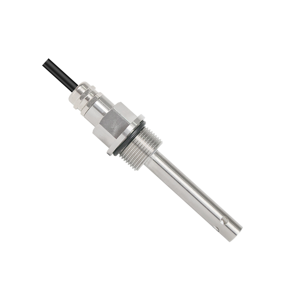
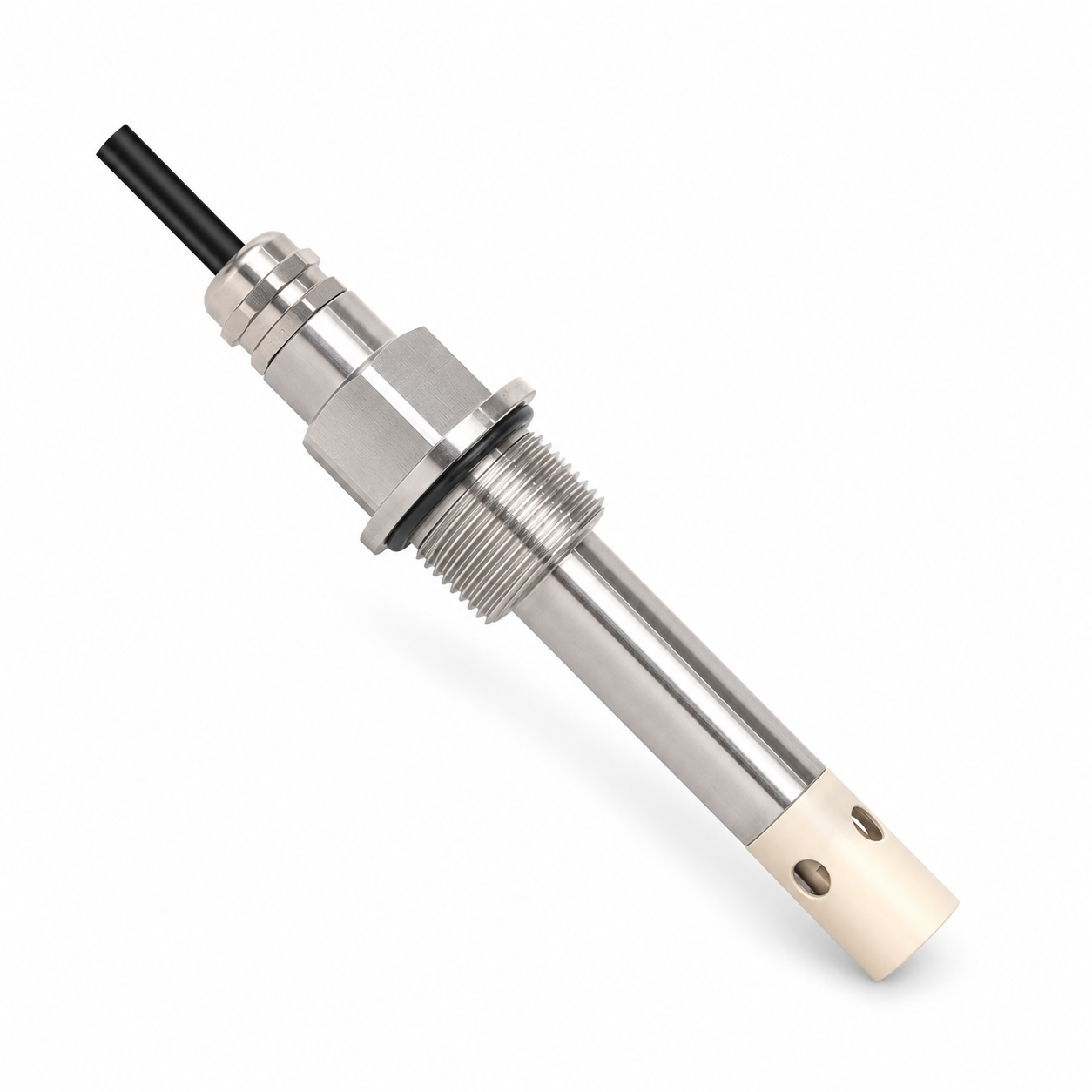
Coolant condition can change during operation. Online electrical conductivity (EC) monitoring gives your team a continuous view of conductivity trends, adding useful information to liquid cooling maintenance decisions.
The RIKA RK500-13LC is designed for liquid cooling applications, with two electrode configurations, simultaneous analog and digital outputs, and installation options for different piping arrangements.
APPLICATION
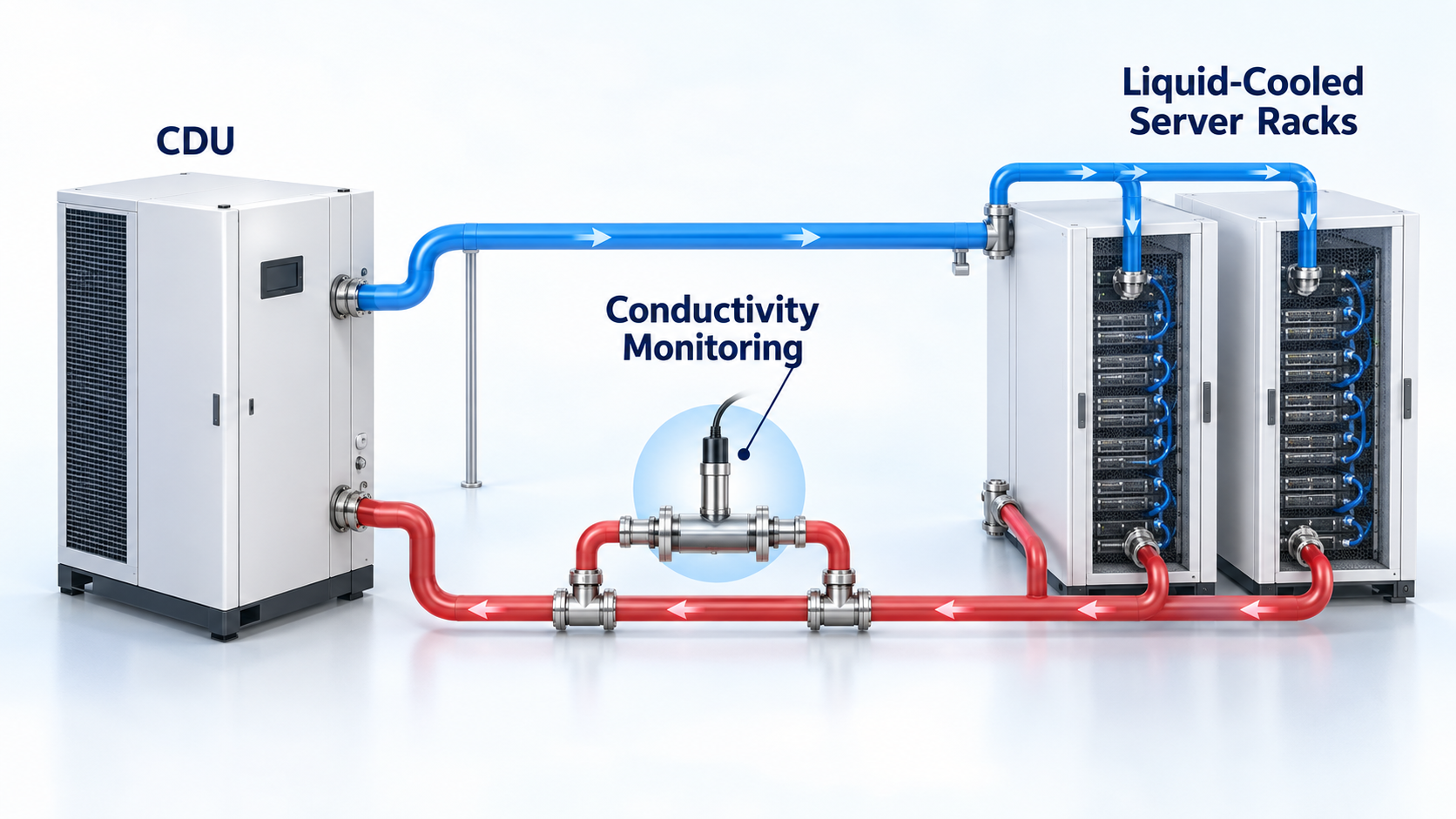
Changes in conductivity can flag changes in coolant condition that deserve investigation. Review readings against the expected baseline for your coolant formulation and the operating limits specified for your equipment.
Conductivity is one part of coolant assessment. Use it alongside other relevant measurements and maintenance observations when deciding what action to take.
PRODUCT FEATURES
Follow conductivity changes as coolant circulates, with online measurement and a specified response time of 1 second. Use trends to prompt checks when readings move outside your system’s expected range.
Anti-polarization technology and electromagnetic isolation help support stable measurements in demanding equipment environments.
Simultaneous 4–20 mA and RS485 outputs connect to compatible monitoring equipment. The integrated design requires no external transmitter and operates from a 7–30 VDC supply.
SENSOR CONFIGURATIONS
Select Type A or Type B according to the expected conductivity range and measurement requirements of your cooling loop.
A 0–20000 µS/cm range can be customized.
Accuracy values above retain the range and temperature conditions stated in specification V5.2.0. Confirm performance requirements for your selected range.
TECHNICAL DATA
| Main material | 316L |
|---|---|
| Standard ranges (µS/cm) |
0-20 0-200 0-2000 |
| Specified accuracy | ±1% FSAt 0-2000 µS/cm, 25°C |
| Main material | 316L + PEEK |
|---|---|
| Standard ranges (µS/cm) |
0-5000 0-10000Custom: 0-20000 µS/cm |
| Specified accuracy | ±1% FSAt 0-10000 µS/cm, 25°C |
FS = full scale. Accuracy applies at the range and temperature shown above. Confirm the required accuracy for other selected ranges.
| Supply voltage | 7-30 VDC |
|---|---|
| Signal outputs | 4-20 mA + RS485Simultaneous analog and digital outputs |
| Power consumption | <0.2 W |
| Response time | 1 second |
| Conductivity resolution | 1 µS/cm |
| Temperature compensation | Thermal resistance |
| Applicable media | Deionized water, PG25 and EG25 |
|---|---|
| Operating temperature | 0 to +60°C |
| Pressure resistance | 1 MPa (10 bar) |
| Probe ingress protection | IP68 |
| O-ring material | EPDM |
| Storage temperature | 10 to 60°C |
| Storage humidity | 20%-90% RH |
| G3/4 | End-face seal |
|---|---|
| NPT3/4 | Upper and lower threadsThread seal |
| 50.5 chuck | Gasket seal |
| Cable termination | M16 connector or direct cable |
|---|---|
| Cable length | 5 m standardOther cable lengths can be customized |
Specification V5.2.0. Confirm material compatibility for your exact coolant formulation.
INSTALLATION
Use a bypass pipe section for easier maintenance and select a location with stable flow. Vertical upward flow is preferred; suitable horizontal piping positions are also supported.
Keep the sensing area free from trapped gas and deposits. Avoid high-point gas traps, low-point sediment zones, vertical downward flow and locations downstream of pressure-reducing sections.
For the M16 connector option, allow at least 70 mm of cable outlet clearance.
SPECIFY YOUR RK500-13LC
Share your coolant type and concentration, expected conductivity range, operating temperature and pressure, process connection, and controller input requirements. Include your preferred cable connection and length, if known.
Our team can help review a suitable Type A or Type B configuration for your project.
E-Mail: info@rikasensor.com
After-sales Service: support@rikasensor.com
WhatsApp | WeChat +86 13367318895
E-Mail: info@rikasensor.com
After-sales Service: support@rikasensor.com
Mobile: +86 13367318895
WhatsApp |WeChat
+86 13367318895
Address: Rm104, Building B1, Changsha Island,877 Huijin Road, Yuhua District, Changsha, Hunan Pro. 410116, China.